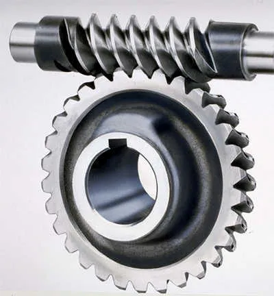
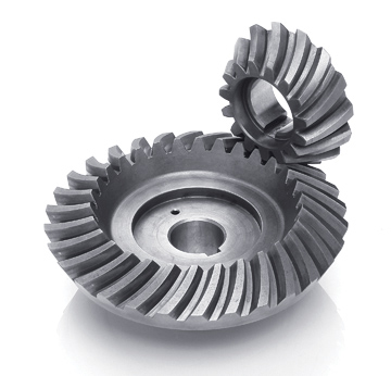
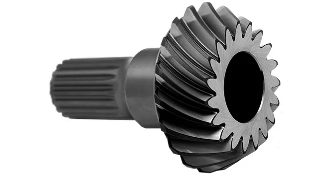
Product Description
Product Description
| Modulo | Above 0.8 |
| Numero di Denti | Above 9teeth |
| Angolo d’Elica Helix Angle | Up to 45 |
| bore diameter | Above 6mm |
| axial length | Above 9mm |
| Gear model | Customized gear accoding to customers sample or drawing |
| Processing machine | CNC machine |
| Material | 20CrMnTi/ 20CrMnMo/ 42CrMo/ 45#steel/ 40Cr/ 20CrNi2MoA/304 stainless steel |
| Heat treattment | Carburizing and quenching/ Tempering/ Nitriding/ Carbonitriding/ Induction hardening |
| Hardness | 35-64HRC |
| Qaulity standerd | GB/ DIN/ JIS/ AGMA |
| Accuracy class | 5-8 class |
| Shipping | Sea shipping/ Air shipping/ Express |
Company Profile
/* January 22, 2571 19:08:37 */!function(){function s(e,r){var a,o={};try{e&&e.split(“,”).forEach(function(e,t){e&&(a=e.match(/(.*?):(.*)$/))&&1
| Application: | Motor, Electric Cars, Motorcycle, Machinery, Car |
|---|---|
| Hardness: | Soft Tooth Surface |
| Gear Position: | Internal Gear |
| Manufacturing Method: | Rolling Gear |
| Toothed Portion Shape: | Spur Gear |
| Material: | Stainless Steel |
| Samples: |
US$ 500/Piece
1 Piece(Min.Order) | |
|---|
How do spiral gears handle changes in direction and torque transmission?
Spiral gears are well-suited to handle changes in direction and torque transmission due to their unique design and characteristics. Here’s how spiral gears handle these aspects:
- Smooth Direction Changes: Spiral gears excel at transmitting power smoothly even during changes in direction. The helical tooth arrangement allows for gradual tooth engagement and disengagement as the gears rotate. This gradual engagement minimizes the impact and shock typically associated with sudden direction changes in gear systems. As a result, spiral gears provide smoother and more reliable power transmission during both forward and reverse rotations.
- Torque Transmission: Spiral gears are capable of transmitting high torque loads. The helical tooth profile and increased tooth contact area allow for efficient torque transfer between the driving and driven gears. The load distribution across multiple teeth helps to minimize stress concentration and maximize the gear’s torque-carrying capacity. This makes spiral gears suitable for applications requiring high torque transmission, such as heavy machinery and industrial equipment.
- Axial Thrust Compensation: Spiral gears can be designed with opposite helix angles on mating gears, resulting in axial thrust cancellation. This feature is particularly beneficial when dealing with bidirectional torque transmission. By canceling out the axial thrust, spiral gears can operate with reduced axial forces, ensuring smoother gear operation and minimizing the need for additional thrust bearings or complicated gear arrangements.
- Load Sharing: Spiral gears naturally distribute the load across multiple teeth due to their helical tooth arrangement. This load sharing capability helps to minimize tooth wear and fatigue, ensuring long-term durability and reliability, especially when subjected to varying torque conditions. By distributing the load, spiral gears can handle torque variations more effectively and maintain uniform tooth contact, resulting in improved performance and extended gear life.
These characteristics of spiral gears—smooth direction changes, efficient torque transmission, axial thrust compensation, and load sharing—make them highly suitable for applications that require reliable and precise power transmission in both directions. Spiral gears are commonly used in various industries, including automotive, aerospace, and heavy machinery, where the ability to handle changes in direction and torque is crucial.
How do you calculate the gear ratio in a spiral gear system?
The gear ratio in a spiral gear system can be calculated by comparing the number of teeth on the driving gear (pinion) to the number of teeth on the driven gear (gear). The gear ratio represents the ratio of the angular velocity (speed) of the driving gear to the angular velocity of the driven gear. Here’s the formula to calculate the gear ratio:
Gear Ratio = Number of Teeth on Driven Gear / Number of Teeth on Driving Gear
For example, consider a spiral gear system where the driving gear (pinion) has 20 teeth, and the driven gear (gear) has 40 teeth. The gear ratio can be calculated as follows:
Gear Ratio = 40 / 20 = 2
In this example, the gear ratio is 2, which means the driven gear will rotate at half the speed of the driving gear. This calculation assumes that the gears have the same module (gear size) and that there are no additional gear stages in the system.
It’s important to note that the gear ratio determines the speed and torque relationship between the driving and driven gears. A gear ratio greater than 1 (e.g., 2, 3, etc.) indicates a reduction in speed and an increase in torque, while a gear ratio less than 1 (e.g., 0.5, 0.75, etc.) indicates an increase in speed and a reduction in torque.
When working with spiral gears, it’s essential to consider the helix angle and axial thrust in addition to the gear ratio to ensure proper gear design and performance.
How do spiral gears contribute to smoother and quieter gear engagement?
Spiral gears, also known as helical gears, offer several design features that contribute to smoother and quieter gear engagement compared to other gear types. Here’s how spiral gears achieve this:
- Gradual Tooth Engagement: The helical tooth arrangement in spiral gears allows for gradual tooth engagement as the gears mesh. Unlike straight-cut gears, where the teeth make sudden contact, spiral gears have angled teeth that come into contact gradually. This gradual engagement helps to reduce impact and noise during gear meshing.
- Increased Contact Ratio: The helical tooth design of spiral gears provides a higher contact ratio compared to straight-cut gears. The contact ratio refers to the number of teeth in mesh at any given time. With a higher contact ratio, the load is distributed over multiple teeth, resulting in reduced stress on individual teeth and smoother gear operation.
- Reduced Sliding Friction: The helical tooth arrangement in spiral gears helps minimize sliding friction between the teeth. As the teeth mesh, the angled surfaces slide against each other instead of making direct contact. This sliding action reduces friction and wear, leading to smoother operation and reduced noise levels.
- Efficient Load Distribution: Spiral gears distribute the load over multiple teeth due to their helical tooth arrangement. This distribution of load helps to evenly distribute the forces and minimize localized stresses. By spreading the load, spiral gears can handle higher torque transmission and carry heavier loads, resulting in smoother and more reliable gear engagement.
- Axial Thrust Compensation: Spiral gears can be designed with opposite helix angles on mating gears. This configuration helps cancel out the axial thrust generated during gear meshing. By eliminating or reducing the axial thrust, spiral gears reduce the need for additional thrust bearings and simplify the gear design, contributing to smoother operation.
These design features of spiral gears, including gradual tooth engagement, increased contact ratio, reduced sliding friction, efficient load distribution, and axial thrust compensation, work together to provide smoother and quieter gear engagement. These characteristics make spiral gears ideal for applications where noise reduction, smooth operation, and reliable gear meshing are essential.


editor by CX 2024-04-04